Newly uploaded TSBs July/August 2024:
Stay updated with the newly uploaded TSBs for July and August 2024. With 229 new TSBs and 99 updates, we provide vital information to help auto mechanics tackle the latest automotive challenges. These bulletins, including common issues like coolant loss and A/C failure in hybrid models, are designed to keep your workshop running smoothly and efficiently.
Example 1:
TSB NO. 11084 – Coolant Loss and A/C Issues in VAG Hybrid Models:
In the newly uploaded TSBs, key issues such as coolant loss in hybrid models have been highlighted. In certain VAG hybrid models, such as the Audi A3, VW Golf, and Skoda Octavia, a common but puzzling issue involving coolant loss and sometimes air conditioning failure can occur. This TSB addresses the underlying causes and provides practical solutions for these models, helping to save time in the workshop.
Typical Symptoms:
- Coolant loss in the high-voltage coolant reservoir: This cooling system is crucial for the hybrid battery and other high-voltage components.
- A/C system underperforming: The air conditioning may fail to cool properly due to refrigerant pressure issues.
- Multiple fault codes stored, such as:
B10ABF0 – A/C Refrigerant Pressure too Low (Intermittent)
P0C4A00 – Hybrid/High-Voltage Battery Coolant Pump 1 – Unrealistic Signal
P139C00 – Sensor 2 for Coolant Indicator, Low Fluid Level
P16C600 – Additional Refrigerant Pump, Dry Running
These PHEV models have two separate coolant reservoirs:
A high-temperature circuit for the combustion engine.
A low-temperature circuit for the EV system, including the EV battery.
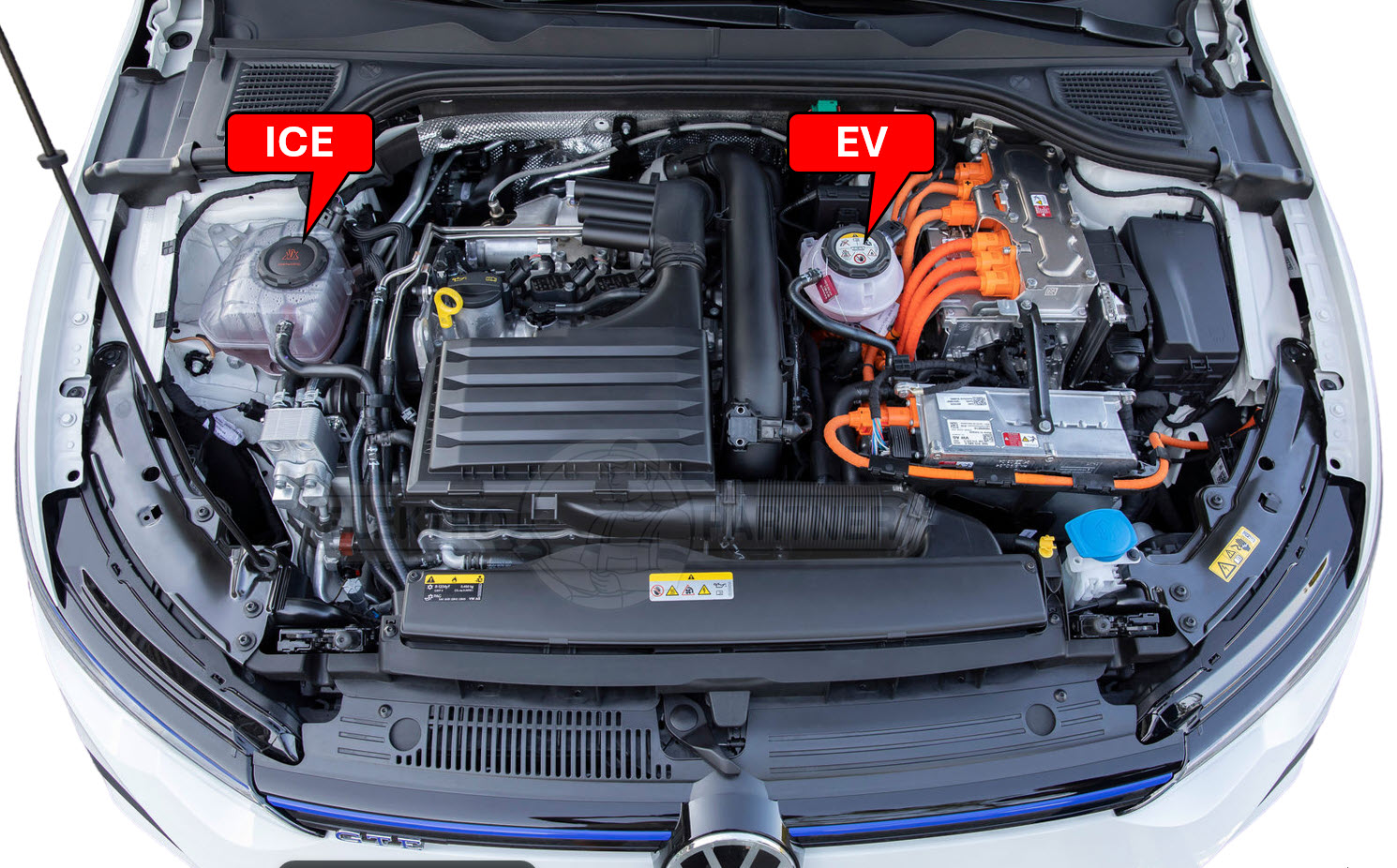
The low-temperature circuit (for the EV system) is cooled via the Electric Climate Compressor V470, which removes heat from the coolant using a circulation pump V590, maintaining the temperature between 20-40°C. The heat from the coolant fluid is transferred to the refrigerant through the high-voltage heat exchanger, commonly referred to as the “Chiller.”
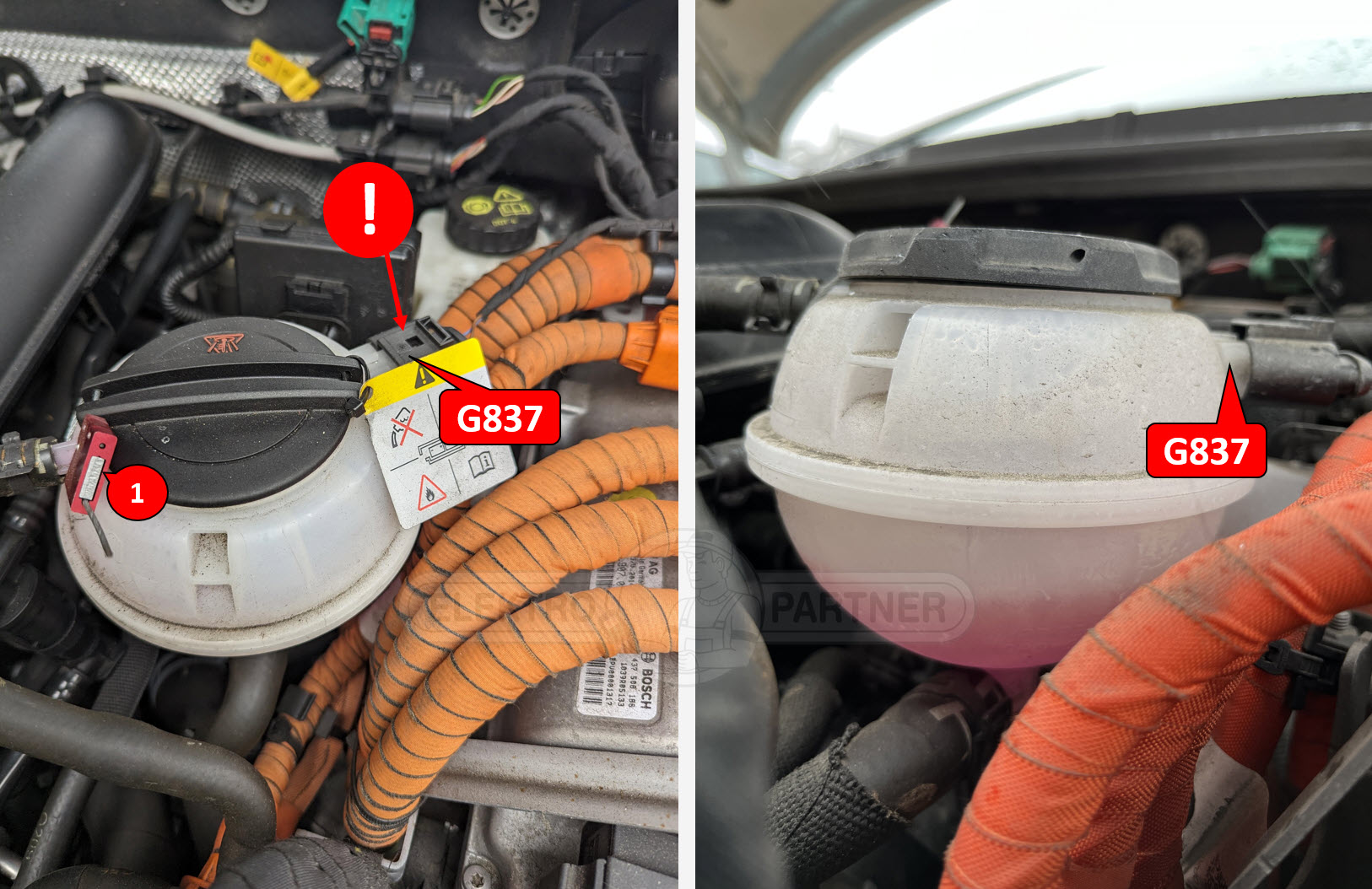
If coolant is missing from the sealed reservoir (1), there may be an internal battery leak. This requires caution, as many warning lights will illuminate to alert the driver if coolant is missing. If an insulation fault is also reported, the repair should be assigned to a certified EV technician due to the potential instability of the battery.
If the leak is external to the battery, you can repair it and refill the coolant. However, ensure that the cooling system is properly bled according to factory guidelines using a diagnostic tool. Air trapped in the cooling circuit can cause the battery to overheat. Due to the critical nature of this coolant circuit, the reservoir is monitored by a level sensor (G837).
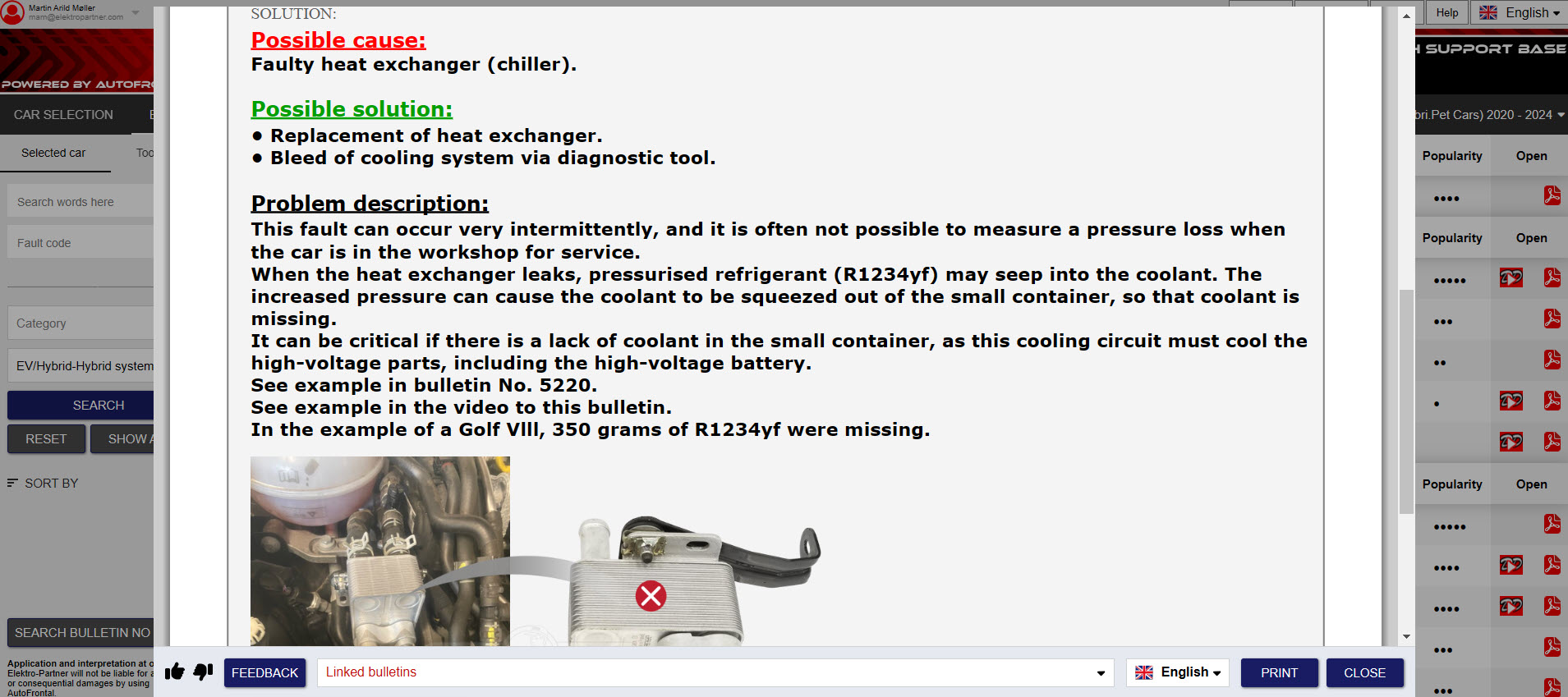
The problem with missing coolant fluid in the EV-coolant reservoir is usually traced to a leak in the chiller, which transfers heat between the refrigerant and the coolant for battery cooling (as previously mentioned). Due to the higher pressure in the refrigerant system, a leak in the chiller forces refrigerant into the coolant system, effectively “pushing” the coolant out of the reservoir. This leads to coolant loss and triggers multiple fault codes.
Note: Depending on the size of the leak in the chiller, this fault may not trigger any fault codes related to the refrigerant system in the early stages of the leak. In such cases, the only noticeable symptom may be the loss of coolant.

This issue can be challenging to diagnose due to its intermittent nature, but understanding the chiller’s role in these systems will help technicians resolve it faster.
Below is a video showing the symptoms of this problem when there is a major leak in the chiller.
This TSB is easily found in DDTSB by searching for keywords such as “Coolant” or by selecting one of the dynamic pre-selected symptoms, like EV/Hybrid system failure. You can also search for relevant fault codes (if any are stored) to locate the TSB more efficiently. This TSB includes both a PDF guide and a video, thanks to contributions from our users.
New DDTSB No. 11084
Example 2:
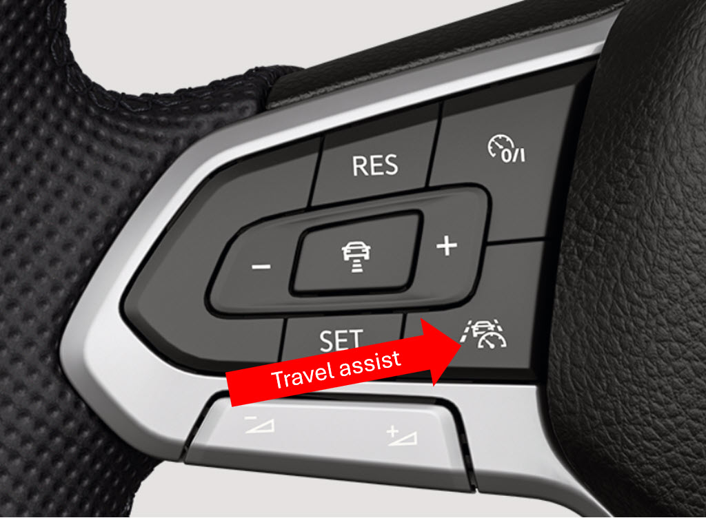
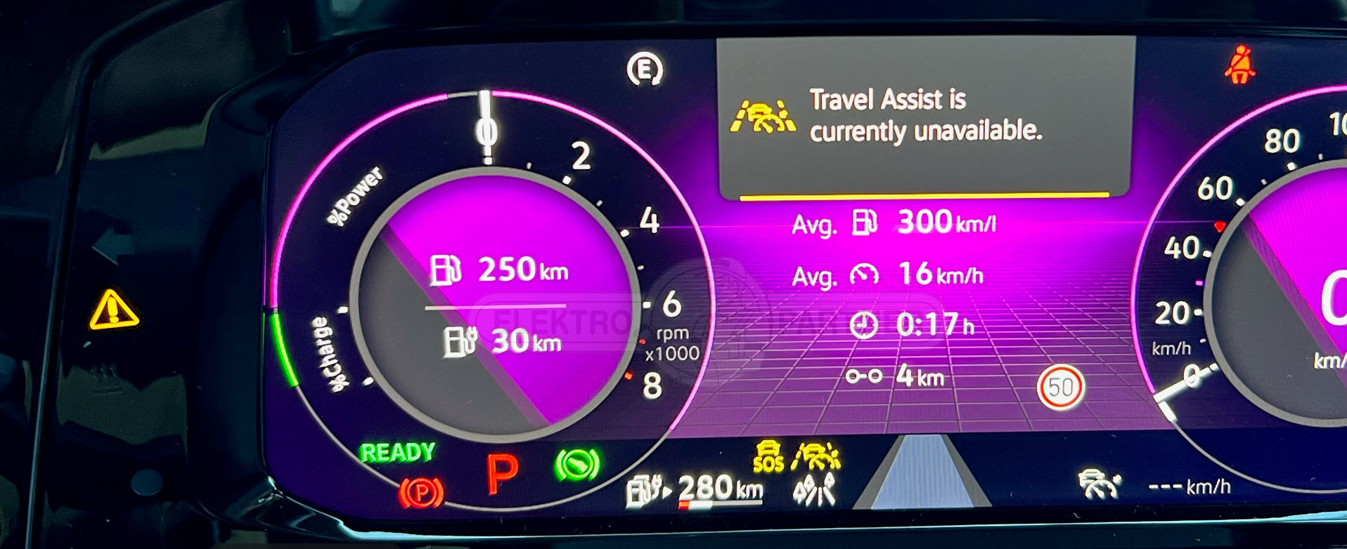
Travel Assist Fault on Volkswagen Models:
Modern Volkswagen models from 2020 onwards are equipped with Travel Assist, an advanced driving assistance system that allows the car to use lane assist and ADAS (Advanced Driver Assistance System) as long as the driver is merely touching the steering wheel. This differs from previous models, where the system required a small torque or correction in the steering wheel to consistently detect that the driver was paying attention to the road.
The new system uses a Hands-On Detection (HOD) touch sensor inside the steering wheel to detect the driver’s presence, making it more convenient compared to the previous torque-based detection system. This system is part of Level 2 driver automation (Partial Automation), where drivers can hand over responsibility for both longitudinal and lateral guidance to the system in specific situations. However, the driver must always be ready to take control of the vehicle when necessary.
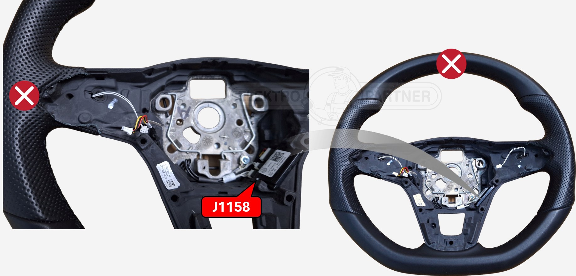
The steering wheel is constructed with multiple layers, including a steering wheel skeleton, two layers of foam, a mat with a capacitive sensor, and a leather cover. The capacitive sensor detects when the driver touches the wheel. It is embedded between the foam layers and connected to the steering wheel contact detection control unit J1158. This unit supplies an alternating voltage to the measuring electrodes. A very low capacitance is created when no objects touch the wheel, resulting in a low current flow between the electrode and body earth. The mat consists of two electrodes: a screening electrode, which insulates the sensing electrode from the inner part of the wheel, and a sensing electrode that acts like a capacitor plate. The vehicle body serves as the second plate connected to earth, while foam, leather, and air act as the dielectric. The control unit sends signals to the adaptive cruise control unit J428 via the LIN bus, also connecting to the multifunction steering wheel control unit J453. The system ensures the driver’s hands are on the wheel, which is required for the proper operation of the Travel Assist system. Unfortunately, workshops are increasingly reporting errors with this system. Since the sensor is integrated into the steering wheel, fixing the issue requires a replacement of the entire steering wheel, which can be quite expensive.
Common Fault Codes:
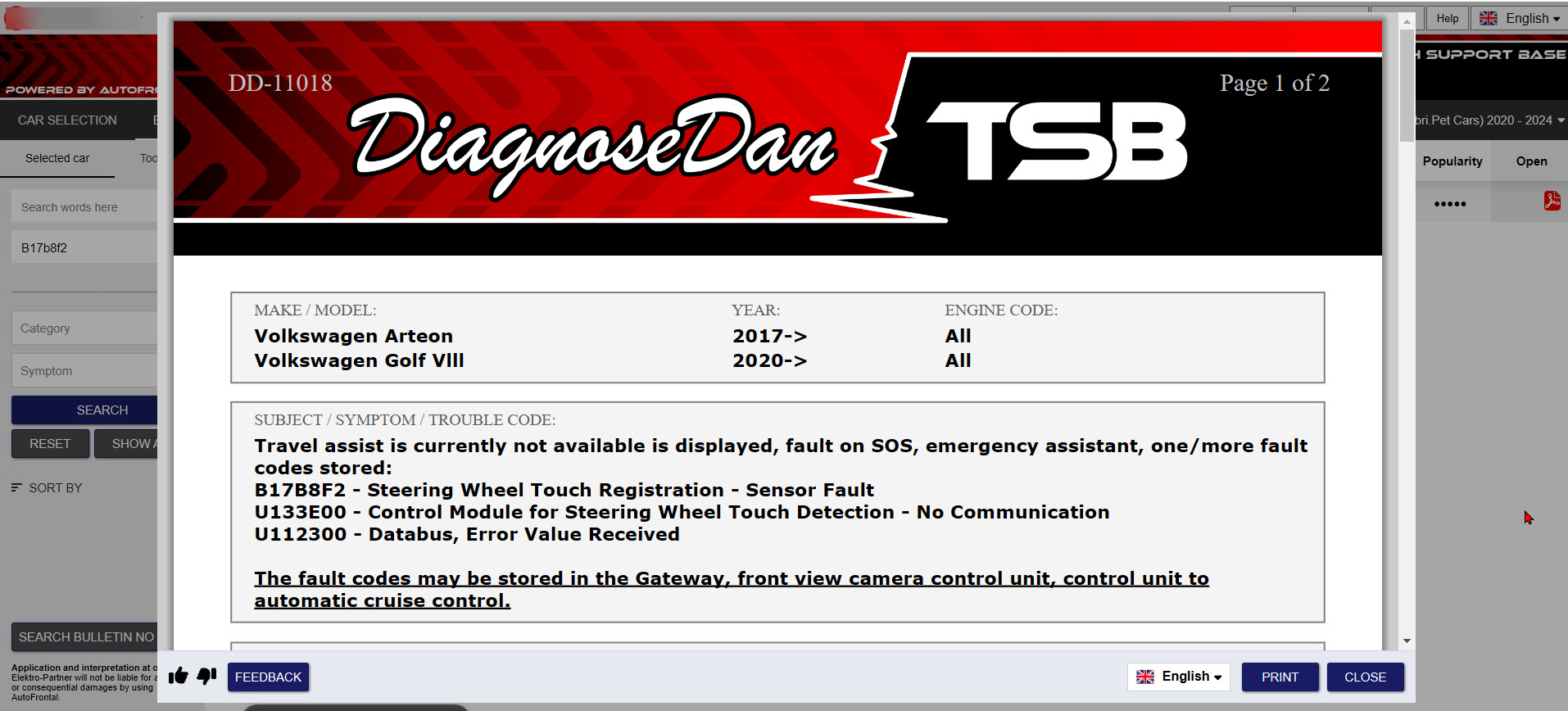
When Travel Assist malfunctions, the following fault codes may be logged:
– B17B8F2 – Steering Wheel Touch Registration – Sensor Fault
– U133E00 – Control Module for Steering Wheel Touch Detection – No Communication
– U112300 – Databus, Error Value Received
Warnings:
Practical Solution:
- Check for service campaigns: The manufacture may have released a service action on certain models to resolve this known issue.
- Replace the steering wheel: If the touch sensor mat is faulty, the entire steering wheel will need to be replaced, as the sensor is integrated within it.
- Inspect Linbus communication lines: Ensure proper communication between the sensor control unit and the vehicle’s Gateway to rule out wiring issues.
- Reset the system: After replacing the necessary components, perform a system reset to clear fault codes and confirm proper operation.
Final Note:
Due to the high cost of a new steering wheel, some workshops choose to implement a “cheat” fix that tricks the travel assist system into thinking the driver always has their hands on the steering wheel. We advise professional workshops to think twice before doing this, as it could lead to dangerous situations where the driver is able to drive without touching the steering wheel. If an accident occurs and this modification is found to be the cause, the workshop responsible could face serious consequences.
New DDTSB No. 11018
Example 3:
Renault / Dacia GPF problems:
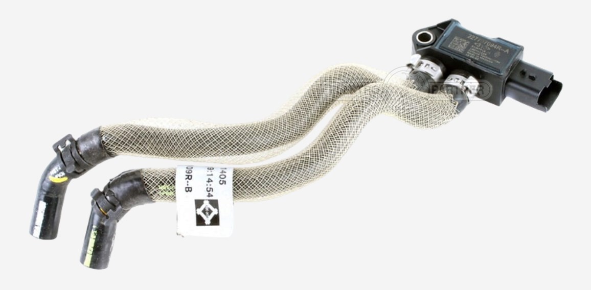
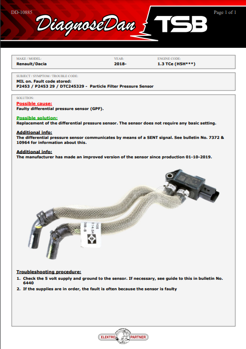
Technicians working on Renault and Dacia models with the 1.3 TCe engine (H5H), particularly those from 2018 onward, may encounter issues with the Gasoline Particulate Filter (GPF) system. A common problem is the failure of the differential pressure sensor, which monitors the GPF’s efficiency. When this sensor fails, it often triggers the check engine light, storing fault codes like P2453 / P2453 29 / DTC245329 (depending of how your scanntool interpretes the fault code)
The differential pressure sensor plays a crucial role in monitoring the performance of the Gasoline Particulate Filter (GPF) system. However, diagnosing issues with this sensor can be particularly challenging due to its use of SENT (Single Edge Nibble Transmission) signals. Many technicians may not realize that the sensor operates with SENT, which could lead to misdiagnosis. If you attempt to diagnose the sensor using a traditional voltmeter, you might not observe significant voltage changes during driving, leading you to investigate the wrong problem.
Since around 2017, more and more sensors in modern vehicles have been using SENT technology. The challenge for many technicians is simply being aware that the sensor they are dealing with operates on a SENT communication system. Without this knowledge, technicians may misinterpret sensor readings and mistakenly diagnose the GPF itself as faulty, rather than recognizing the true issue with the SENT-based differential pressure sensor.
The intermittent nature of these sensor failures adds another layer of complexity to the diagnosis process. Without the proper tools or understanding of how to interpret SENT signals, diagnosing the exact fault becomes difficult, further complicating repairs.
- Practical Solution
Check the wiring: Verify the integrity of the wiring between the sensor unit and ECU. Ensure the 5V supply and ground are stable. - Replace the sensor unit: If wiring checks out, replacing the bundled sensor unit is typically the solution, as all sensors are housed together.
New DDTSB No. 10885:
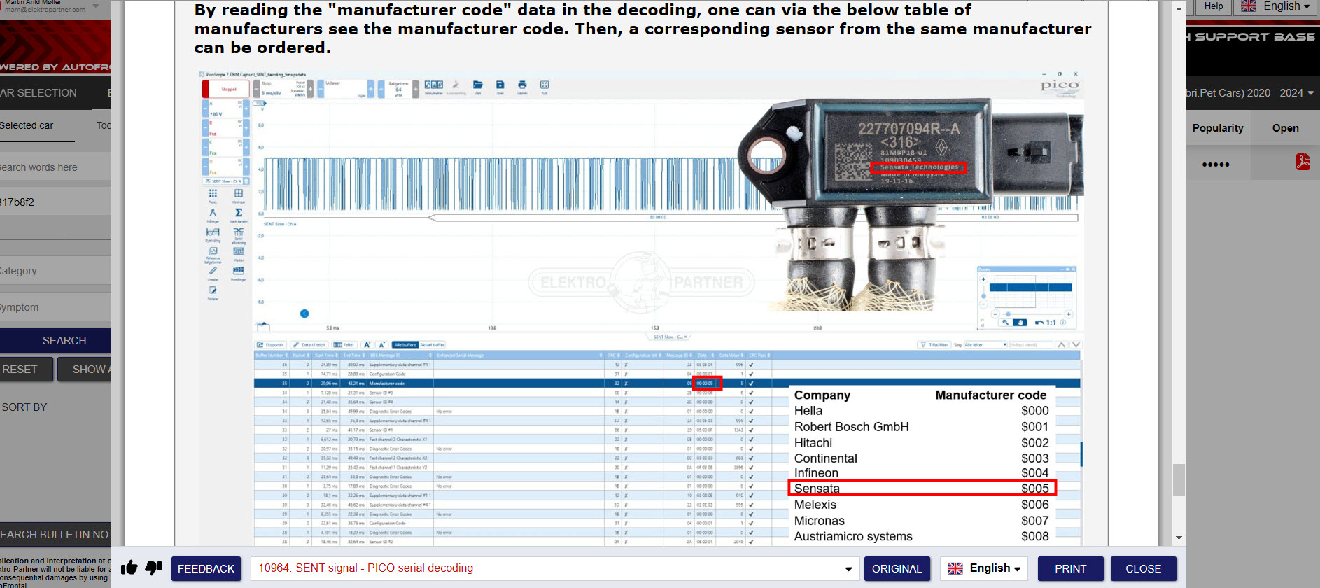
This issue highlights the complexity of modern exhaust monitoring systems, but it can be resolved efficiently with the right diagnostic approach. If you’re unaware that these sensors use SENT signals, it could mislead your diagnosis. In this TSB, we also reference two measurement methods (self-study programs) that explain the basic operating principles of SENT signals and how to use the PICO decoding procedure to analyze the signal.
Boost your workshop’s efficiency with DDTSB. Access a vast database of thousands of exclusive aftermarket TSBs to enhance diagnostic precision, save time, and get the repair right the first time. DDTSB: Your investment in faster solutions and higher profitability. Time is money—save both with DDTSB